Uninterruptible power supplies (UPS)
Introduction
An uninterruptible power supply, also uninterruptible power source, UPS or battery/flywheel
backup, is an electrical apparatus that provides emergency power to a load when
the input power source, typically mains power, fails. A UPS differs from an auxiliary
or emergency power system or standby generator in that it will provide near-instantaneous
protection from input power interruptions, by supplying energy stored in batteries,
supercapacitors, or flywheels. The on-battery runtime of most uninterruptible power
sources is relatively short (only a few minutes) but sufficient to start a standby
power source or properly shut down the protected equipment. A UPS is typically used
to protect hardware such as computers, data centers, telecommunication equipment
or other electrical equipment where an unexpected power disruption could cause injuries,
fatalities, serious business disruption or data loss. UPS units range in size from
units designed to protect a single computer without a video monitor (around 200
VA rating) to large units powering entire data centers or buildings
Common power problems
The primary role of any UPS is to provide short-term power when the input power
source fails. However, most UPS units are also capable in varying degrees of correcting
common utility power problems:
-
Voltage spike or sustained overvoltage
-
Momentary
or sustained reduction in input voltage
-
Noise,
defined as a high frequency transient or oscillation, usually injected into the
line by nearby equipment
-
Instability
of the mains frequency
-
Harmonic
distortion: defined as a departure from the ideal sinusoidal waveform expected on
the line
UPS units are divided into categories based on which of the above problems they
address and some manufacturers categorize their products in accordance with the
number of power-related problems they address
Technologies
The three general categories of modern UPS systems are on-line, line-interactive
or standby.An on-line UPS uses a “double conversion” method of accepting AC input,
rectifying to DC for passing through the rechargeable battery (or battery strings),
then inverting back to 120 V/230 V AC for powering the protected equipment. A line-interactive
UPS maintains the inverter in line and redirects the battery’s DC current path from
the normal charging mode to supplying current when power is lost. In a standby (“off-line”)
system the load is powered directly by the input power and the backup power circuitry
is only invoked when the utility power fails. Most UPS below 1 kVA are of the line-interactive
or standby variety which are usually less expensive. For large power units, dynamic
uninterruptible power supplies are sometimes used. A synchronous motor/alternator
is connected on the mains via a choke. Energy is stored in a flywheel. When the
mains power fails, an Eddy-current regulation maintains the power on the load as
long as the flywheel’s energy is not exhausted. DUPS are sometimes combined or integrated
with a diesel generator that is turned on after a brief delay, forming a diesel
rotary uninterruptible power supply (DRUPS).
Offline/standby
The offline/standby UPS (SPS) offers only the most basic features, providing surge
protection and battery backup. The protected equipment is normally connected directly
to incoming utility power. When the incoming voltage falls below or rises above
a predetermined level the SPS turns on its internal DC-AC inverter circuitry, which
is powered from an internal storage battery. The UPS then mechanically switches
the connected equipment on to its DC-AC inverter output. The switchover time can
be as long as 25 milliseconds depending on the amount of time it takes the standby
UPS to detect the lost utility voltage. The UPS will be designed to power certain
equipment, such as a personal computer, without any objectionable dip or brownout
to that device.
Offline / standby UPS. Typical protection time: 0–20 minutes. Capacity expansion:
Usually not available
Line-interactive
The line-interactive UPS is similar in operation to a standby UPS, but with the
addition of a multi-tap variable-voltage autotransformer. This is a special type
of transformer that can add or subtract powered coils of wire, thereby increasing
or decreasing the magnetic field and the output voltage of the transformer. This
is also known as a Buck–boost transformer. This type of UPS is able to tolerate
continuous under voltage brownouts and overvoltage surges without consuming the
limited reserve battery power. It instead compensates by automatically selecting
different power taps on the autotransformer. Depending on the design, changing the
autotransformer tap can cause a very brief output power disruption. Which may cause
UPSs equipped with a power-loss alarm to “chirp” for a moment. This has become popular
even in the cheapest UPSs because it takes advantage of components already included.
The main 50/60 Hz transformer used to convert between line voltage and battery voltage
needs to provide two slightly different turns ratios: One to convert the battery
output voltage (typically a multiple of 12 V) to line voltage, and a second one
to convert the line voltage to a slightly higher battery charging voltage (such
as a multiple of 14 V). The difference between the two voltages is because charging
a battery requires a delta voltage (up to 13–14 V for charging a 12 V battery).
Furthermore, it is easier to do the switching on the line-voltage side of the transformer
because of the lower currents on that side. To gain the buck/boost feature, all
that is required is two separate switches so that the AC input can be connected
to one of the two primary taps, while the load is connected to the other, thus using
the main transformer’s primary windings as an autotransformer. The battery can still
be charged while “bucking” an overvoltage, but while “boosting” an under voltage,
the transformer output is too low to charge the batteries. Autotransformers can
be engineered to cover a wide range of varying input voltages, but this requires
more taps and increases complexity, and expense of the UPS. It is common for the
autotransformer to cover a range only from about 90 V to 140 V for 120 V power,
and then switch to battery if the voltage goes much higher or lower than that range.
In low-voltage conditions the UPS will use more current than normal so it may need
a higher current circuit than a normal device. For example to power a 1000-W device
at 120 V, the UPS will draw 8.33 A. If a brownout occurs and the voltage drops to
100 V, the UPS will draw 10 A to compensate. This also works in reverse, so that
in an overvoltage condition, the UPS will need less current.

Line-interactive UPS. Typical protection time: 5–30 minutes. Capacity expansion:
Several hours
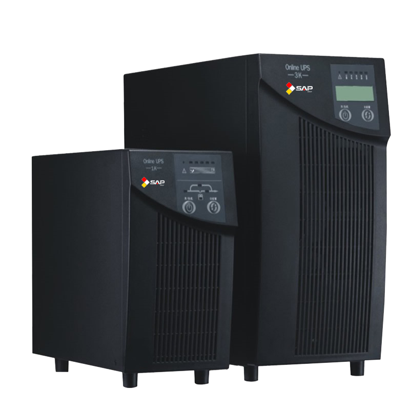
Online/double-conversion
The online UPS is ideal for environments where electrical isolation is necessary
or for equipment that is very sensitive to power fluctuations. Although once previously
reserved for very large installations of 10 kW or more, advances in technology have
now permitted it to be available as a common consumer device, supplying 500 W or
less. The initial cost of the online UPS may be higher, but its total cost of ownership
is generally lower due to longer battery life. The online UPS may be necessary when
the power environment is “noisy”, when utility power sags, outages and other anomalies
are frequent, when protection of sensitive IT equipment loads is required, or when
operation from an extended-run backup generator is necessary. The basic technology
of the online UPS is the same as in a standby or line-interactive UPS. However it
typically costs much more, due to it having a much greater current AC-to-DC battery-charger/rectifier,
and with the rectifier and inverter designed to run continuously with improved cooling
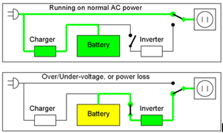
systems. It is called a double-conversion UPS due to the rectifier directly driving
the inverter, even when powered from normal AC current. In an online UPS, the batteries
are always connected to the inverter, so that no power transfer switches are necessary.
When power loss occurs, the rectifier simply drops out of the circuit and the batteries
keep the power steady and unchanged. When power is restored, the rectifier resumes
carrying most of the load and begins charging the batteries, though the charging
current may be limited to prevent the high-power rectifier from overheating the
batteries and boiling off the electrolyte. The main advantage to the on-line UPS
is its ability to provide an electrical firewall between the incoming utility power
and sensitive electronic equipment.
Other designs
Hybrid topology / double conversion on demand
These hybrid designs do not have official designations, although one name used by
HP and Eaton is “double conversion on demand”.This style of UPS is targeted towards
high-efficiency applications while still maintaining the features and protection
level offered by double conversion.A hybrid (double conversion on demand) UPS operates
as an off-line/standby UPS when power conditions are within a certain preset window.
This allows the UPS to achieve very high efficiency ratings. When the power conditions
fluctuate outside of the predefined windows, the UPS switches to online/double-conversion
operation. In double-conversion mode the UPS can adjust for voltage variations without
having to use battery power, can filter out line noise and control frequency. Examples
of this hybrid/double conversion on demand UPS design are the HP R8000, HP R12000,
HP RP12000/3 and the Eaton BladeUPS.
Ferro-resonant
Ferro-resonant units operate in the same way as a standby UPS unit; however, they
are online with the exception that a ferro-resonant transformer is used to filter
the output. This transformer is designed to hold energy long enough to cover the
time between switching from line power to battery power and effectively eliminates
the transfer time. Many ferro-resonant UPSs are 82–88% efficient (AC/DC-AC) and
offer excellent isolation. The transformer has three windings, one for ordinary
mains power, the second for rectified battery power, and the third for output AC
power to the load.This once was the dominant type of UPS and is limited to around
the 150 kVA range. These units are still mainly used in some industrial settings
(oil and gas, petrochemical, chemical, utility, and heavy industry markets) due
to the robust nature of the UPS. Many ferro-resonant UPSs utilizing controlled ferro
technology may not interact with power-factor-correcting equipment.
DC power
A UPS designed for powering DC equipment is very similar to an online UPS, except
that it does not need an output inverter. Also, if the UPS’s battery voltage is
matched with the voltage the device needs, the device’s power supply will not be
needed either. Since one or more power conversion steps are eliminated, this increases
efficiency and run time. Many systems used in telecommunications use an extra-low
voltage “common battery” 48 V DC power, because it has less restrictive safety regulations,
such as being installed in conduit and junction boxes. DC has typically been the
dominant power source for telecommunications, and AC has typically been the dominant
source for computers and servers. There has been much experimentation with 48 V
DC power for computer servers, in the hope of reducing the likelihood of failure
and the cost of equipment. However, to supply the same amount of power, the current
would be higher than an equivalent 115 V or 230 V circuit; greater current requires
larger conductors, or more energy lost as heat. Most PCs can be powered with 325
V DC. This is because most ATX switching power supplies convert the AC input voltage
to approximately 325 V DC (230 × √2). On units with a voltage selector switch, the
115 V setting enables a voltage doubler that puts the top half of the AC wave in
one capacitor, and the bottom half in the other capacitor. This mode uses half of
the bridge rectifier and runs twice as much current through it. The 230 V setting
simply rectifies the AC using the full bridge rectifier, and puts it into both capacitors.
These two capacitors are hardwired in series. These power supplies can almost always
be safely run on 280–340 V DC long as the selector is in the 230 V position. They
will not work at all with DC power in the 115 V position; with 162 V DC applied,
nothing will happen because only one capacitor is being charged; if 325 V is applied,
the fuse and a surge suppressor or capacitor will blow. Power supplies with Active-PFC
are usually auto-ranging and have no voltage selector switch. They usually have
one input capacitor; it is charged to 320-400 V DC by a boost-mode power supply
that is part of the PFC circuit. It is uncertain how various auto-ranging and Active-PFC
power supplies will respond to having DC power applied when they are expecting AC
50–60 Hz power. A laptop computer is a classic example of a PC with a DC UPS built
in. High voltage DC (380 V) is finding use in some data center applications, and
allows for small power conductors, but is subject to the more complex electrical
code rules for safe containment of high voltages.
Rotary
A rotary UPS uses the inertia of a high-mass spinning flywheel (flywheel energy
storage) to provide short-term ride-through in the event of power loss. The flywheel
also acts as a buffer against power spikes and sags, since such short-term power
events are not able to appreciably affect the rotational speed of the high-mass
flywheel. It is also one of the oldest designs, predating vacuum tubes and integrated
circuits. It can be considered to be on line since it spins continuously under normal
conditions. However, unlike a battery-based UPS, flywheel-based UPS systems typically
provide 10 to 20 seconds of protection before the flywheel has slowed and power
output stops. It is traditionally used in conjunction with standby diesel generators,
providing backup power only for the brief period of time the engine needs to start
running and stabilize its output. The rotary UPS is generally reserved for applications
needing more than 10,000 W of protection, to justify the expense and benefit from
the advantages rotary UPS systems bring. A larger flywheel or multiple flywheels
operating in parallel will increase the reserve running time or capacity. Because
the flywheels are a mechanical power source, it is not necessary to use an electric
motor or generator as an intermediary between it and a diesel engine designed to
provide emergency power. By using a transmission gearbox, the rotational inertia
of the flywheel can be used to directly start up a diesel engine, and once running,
the diesel engine can be used to directly spin the flywheel. Multiple flywheels
can likewise be connected in parallel through mechanical countershafts, without
the need for separate motors and generators for each flywheel. They are normally
designed to provide very high current output compared to a purely electronic UPS,
and are better able to provide inrush current for inductive loads such as motor
startup or compressor loads, as well as medical MRI and cath lab equipment. It is
also able to tolerate short-circuit conditions up to 17 times larger than an electronic
UPS, permitting one device to blow a fuse and fail while other devices still continue
to be powered from the rotary UPS. Its life cycle is usually far greater than a
purely electronic UPS, up to 30 years or more. But they do require periodic downtime
for mechanical maintenance, such as ball bearing replacement. In larger systems
redundancy of the system ensures the availability of processes during this maintenance.
Battery-based designs do not require downtime if the batteries can be hot-swapped,
which is usually the case for larger units. Newer rotary units use technologies
such as magnetic bearings and air-evacuated enclosures to increase standby efficiency
and reduce maintenance to very low levels. Typically, the high-mass flywheel is
used in conjunction with a motor-generator system. These units can be configured
as:
-
A
motor driving a mechanically connected generator,
-
A
combined synchronous motor and generator wound in alternating slots of a single
rotor and stator,
-
A
hybrid rotary UPS, designed similar to an online UPS, except that it uses the flywheel
in place of batteries. The rectifier drives a motor to spin the flywheel, while
a generator uses the flywheel to power the inverter.
In case No. 3 the motor generator can be synchronous/synchronous or induction/synchronous.
The motor side of the unit in case Nos. 2 and 3 can be driven directly by an AC
power source (typically when in inverter bypass), a 6-step double-conversion motor
drive, or a 6-pulse inverter. Case No. 1 uses an integrated flywheel as a short-term
energy source instead of batteries to allow time for external, electrically coupled
genets to start and be brought online. Case Nos. 2 and 3 can use batteries or a
free-standing electrically coupled flywheel as the short-term energy source.
Applications
N+1
In large business environments where reliability is of great importance, a single
huge UPS can also be a single point of failure that can disrupt many other systems.
To provide greater reliability, multiple smaller UPS modules and batteries can be
integrated together to provide redundant power protection equivalent to one very
large UPS. “N+1” means that if the load can be supplied by N modules, the installation
will contain N+1 modules. In this way, failure of one module will not impact system
operation.
Multiple redundancy
Many computer servers offer the option of redundant power supplies, so that in the
event of one power supply failing, one or more other power supplies are able to
power the load. This is a critical point – each power supply must be able to power
the entire server by itself. Redundancy is further enhanced by plugging each power
supply into a different circuit (i.e. to a different circuit breaker). Redundant
protection can be extended further yet by connecting each power supply to its own
UPS. This provides double protection from both a power supply failure and a UPS
failure, so that continued operation is assured. This configuration is also referred
to as 1+1 or 2N redundancy. If the budget does not allow for two identical UPS units
then it is common practice to plug one power supply into mains power and the other
into the UPS.
Outdoor use
When a UPS system is placed outdoors, it should have some specific features that
guarantee that it can tolerate weather with no effect on performance. Factors such
as temperature, humidity, rain, and snow among others should be considered by the
manufacturer when designing an outdoor UPS system. Operating temperature ranges
for outdoor UPS systems could be around −40 °C to +55 °C. Outdoor UPS systems can
be pole, ground (pedestal), or host mounted. Outdoor environment could mean extreme
cold, in which case the outdoor UPS system should include a battery heater mat,
or extreme heat, in which case the outdoor UPS system should include a fan system
or an air conditioning system.
Internal systems
UPS systems can be designed to be placed inside a computer chassis. There are two
types of internal UPS. The first type is a miniaturized regular UPS that is made
small enough to fit into a 5.25-inch CD-ROM slot bay of a regular computer chassis.
The other type are re-engineered switching power supplies that utilize dual AC or
DC power sources as inputs and have built-in switching control units.
Machine standards
Measuring efficiency
The way efficiency is measured varies massively in the UPS market, and there are
a number of reasons for this. Many UPS manufacturers claim to have the highest level
of efficiency, often using different sets of criteria in order to reach these figures.
The industry norm can be argued to be anything between 93%-96% when a UPS is in
full operational mode, and to reach these figures companies often put their UPS
in an ideal scenario. Efficiency figures on site are often much closer to the 90%
mark, due to varying power conditions. The perfect scenario will never happen in
reality, due to ongoing voltage sags from the mains and the declining efficiency
of UPS batteries.
Warranty
Warranty on uninterruptible power supplies has varied over the past couple of years,
often depending if a machine is single phase or three phase. Few companies compete
on warranty, with the focus mainly on efficiency and maintenance contracts. The
standard manufacturer’s warranty is anything between 1–2 years and can even be limited
to certain aspects of the machine, often excluding the more expensive items such
as battery replacement. Focusing on one market, companies supplying three phase
however now offer lengthier warranties, with the norm closer to 2 years rather than
the single year.
Difficulties faced with generator use
Power factor
A problem in the combination of a “double conversion” UPS and a generator is the
voltage distortion created by the UPS. The input of a double conversion UPS is essentially
a big rectifier. The current drawn by the UPS is non-sinusoidal. This can cause
the voltage from the AC mains or a generator to also become non-sinusoidal. The
voltage distortion then can cause problems in all electrical equipment connected
to that power source, including the UPS itself. It will also cause more power to
be lost in the wiring supplying power to the UPS due to the spikes in current flow.
This level of “noise” is measured as a percentage of “Total Harmonic Distortion
of the current” (THD (i)). Classic UPS rectifiers have a THD (i) level of around
25–30%. To reduce voltage distortion, this requires heavier mains wiring or generators
more than twice as large as the UPS. There are several solutions to reduce the THD
(i) in a double conversion UPS:
Passive power factor correction:
Classic solutions such as passive filters reduce THD (i) to 5–10% at full load.
They are reliable, but big and only work at full load, and present their own problems
when used in tandem with generators.
Active power factor correction:
An alternative solution is an active filter. Through the use of such a device, THD
(i) can drop to 5% over the full power range. The newest technology in double conversion
UPS units is a rectifier that doesn’t use classic rectifier components (thyristors
and diodes) but high frequency components. A double conversion UPS with an IGBT
rectifier and inductor can have a THD (i) as small as 2%. This completely eliminates
the need to oversize the generator (and transformers), without additional filters,
investment cost, losses, or space.
Communication
Power management (PM) requires
-
The
UPS to report its status to the computer it powers via a communications link such
as a serial port, Ethernet and Simple Network Management Protocol, GSM/GPRS or USB
-
A subsystem in the OS that processes the reports and generates notifications, PM
events, or commands an ordered shut down. Some UPS manufacturers publish their communication
protocols, but other manufacturers use proprietary protocols.
The basic computer-to-UPS control methods are intended for one-to-one signaling
from a single source to a single target. For example, a single UPS may connect to
a single computer to provide status information about the UPS, and allow the computer
to control the UPS. Similarly, the USB protocol is also intended to connect a single
computer to multiple peripheral devices. In some situations it is useful for a single
large UPS to be able to communicate with several protected devices. For traditional
serial or USB control, a signal replication device may be used, which for example
allows one UPS to connect to five computers using serial or USB connections. However,
the splitting is typically only one direction from UPS to the devices to provide
status information. Return control signals may only be permitted from one of the
protected systems to the UPS. As Ethernet has increased in common use since the
1990s, control signals are now commonly sent between a single UPS and multiple computers
using standard Ethernet data communication methods such as TCP/IP. The status and
control information is typically encrypted so that for example an outside hacker
cannot gain control of the UPS and command it to shut down. Distribution of UPS
status and control data requires that all intermediary devices such as Ethernet
switches or serial multiplexers be powered by one or more UPS systems, in order
for the UPS alerts to reach the target systems during a power outage. To avoid the
dependency on Ethernet infrastructure, the UPSs can be connected directly to main
control server by using GSM/GPRS channel also. The SMS or GPRS data packets sent
from UPSs trigger software to shut down the PCs to reduce the load.
Batteries
The run-time for a battery-operated UPS depends on the type and size of batteries
and rate of discharge, and the efficiency of the inverter. The total capacity of
a lead–acid battery is a function of the rate at which it is discharged, which is
described as Peukert’s law. Manufacturers supply run-time rating in minutes for
packaged UPS systems. Larger systems (such as for data centers) require detailed
calculation of the load, inverter efficiency, and battery characteristics to ensure
the required endurance is attained.
Common battery characteristics and load testing
When a lead–acid battery is charged or discharged, this initially affects only the
reacting chemicals, which are at the interface between the electrodes and the electrolyte.
With time, the charge stored in the chemicals at the interface, often called “interface
charge”, spreads by diffusion of these chemicals throughout the volume of the active
material. If a battery has been completely discharged (e.g. the car lights were
left on overnight) and next is given a fast charge for only a few minutes, then
during the short charging time it develops only a charge near the interface. The
battery voltage may rise to be close to the charger voltage so that the charging
current decreases significantly. After a few hours this interface charge will spread
to the volume of the electrode and electrolyte, leading to an interface charge so
low that it may be insufficient to start the car. Due to the interface charge, brief
UPS self-test functions lasting only a few seconds may not accurately reflect the
true runtime capacity of a UPS, and instead an extended recalibration or rundown
test that deeply discharges the battery is needed. The deep discharge testing is
itself damaging to batteries due to the chemicals in the discharged battery starting
to crystallize into highly stable molecular shapes that will not re-dissolve when
the battery is recharged, permanently reducing charge capacity. In lead acid batteries
this is known as sulfation but also affects other types such as nickel cadmium batteries
and lithium batteries. Therefore it is commonly recommended that rundown tests be
performed infrequently, such as every six months to a year
Testing of strings of batteries/cells
Multi-kilowatt commercial UPS systems with large and easily accessible battery banks
are capable of isolating and testing individual cells within a battery string, which
consists of either combined-cell battery units (such as 12-V lead acid batteries)
or individual chemical cells wired in series. Isolating a single cell and installing
a jumper in place of it allows the one battery to be discharge-tested, while the
rest of the battery string remains charged and available to provide protection.
It is also possible to measure the electrical characteristics of individual cells
in a battery string, using intermediate sensor wires that are installed at every
cell-to-cell junction, and monitored both individually and collectively. Battery
strings may also be wired as series-parallel, for example two sets of 20 cells.
In such a situation it is also necessary to monitor current flow between parallel
strings, as current may circulate between the strings to balance out the effects
of weak cells, dead cells with high resistance, or shorted cells. For example, stronger
strings can discharge through weaker strings until voltage imbalances are equalized,
and this must be factored into the individual inter-cell measurements within each
string.
Series-parallel battery interactions
Battery strings wired in series-parallel can develop unusual failure modes due to
interactions between the multiple parallel strings. Defective batteries in one string
can adversely affect the operation and lifespan of good or new batteries in other
strings. These issues also apply to other situations where series-parallel strings
are used, not just in UPS systems but also in electric vehicle applications. Consider
a series-parallel battery arrangement with all good cells, and one becomes shorted
or dead:
-
The
failed cell will reduce the maximum developed voltage for the entire series string
it is within.
-
Other
series strings wired in parallel with the degraded string will now discharge through
the degraded string until their voltage matches the voltage of the degraded string,
potentially overcharging and leading to electrolyte boiling and outgassing from
the remaining good cells in the degraded string. These parallel strings can now
never be fully recharged, as the increased voltage will bleed off through the string
containing the failed battery.
-
Charging
systems may attempt to gauge battery string capacity by measuring overall voltage.
Due to the overall string voltage depletion due to the dead cells, the charging
system may detect this as a state of discharge, and will continuously attempt to
charge the series-parallel strings, which leads to continuous overcharging and damage
to all the cells in the degraded series string containing the damaged battery.
-
If
lead-acid batteries are used, all cells in the formerly good parallel strings will
begin to sulfate due to the inability for them to be fully recharged, resulting
in the storage capacity of these cells being permanently damaged, even if the damaged
cell in the one degraded string is eventually discovered and replaced with a new
one.
The only way to prevent these subtle series-parallel string interactions is by not
using parallel strings at all and using separate charge controllers and inverters
for individual series strings.
Series new/old battery interactions
Even just a single string of batteries wired in series can have adverse interactions
if new batteries are mixed with old batteries. Older batteries tend to have reduced
storage capacity, and so will both discharge faster than new batteries and also
charge to their maximum capacity more rapidly than new batteries. As a mixed string
of new and old batteries is depleted, the string voltage will drop, and when the
old batteries are exhausted the new batteries still have charge available. The newer
cells may continue to discharge through the rest of the string, but due to the low
voltage this energy flow may not be useful, and may be wasted in the old cells as
resistance heating. For cells that are supposed to operate within a specific discharge
window, new cells with more capacity may cause the old cells in the series string
to continue to discharge beyond the safe bottom limit of the discharge window, damaging
the old cells. When recharged, the old cells recharge more rapidly, leading to a
rapid rise of voltage to near the fully charged state, but before the new cells
with more capacity have fully recharged. The charge controller detects the high
voltage of a nearly fully charged string and reduces current flow. The new cells
with more capacity now charge very slowly, so slowly that the chemicals may begin
to crystallize before reaching the fully charged state, reducing new cell capacity
over several charge/discharge cycles until their capacity more closely matches the
old cells in the series string. For such reasons, some industrial UPS management
systems recommend periodic replacement of entire battery arrays potentially using
hundreds of expensive batteries, due to these damaging interactions between new
batteries and old batteries, within and across series and parallel strings.